Concentricity testing systems for rotors
Precise concentricity measurements in production and maintenance
The Hofmann concentricity testing systems from Type UHR enable high-precision concentricity and axial runout measurements of rotors, for example mounted in prisms. Total, mechanical and electrical runout measurements are covered. The systems guarantee maximum accuracy in measurement and ensure the functionality of turbomachinery. Deviations can be detected at an early stage, which optimizes production processes and significantly increases the service life and operational reliability of the machines.
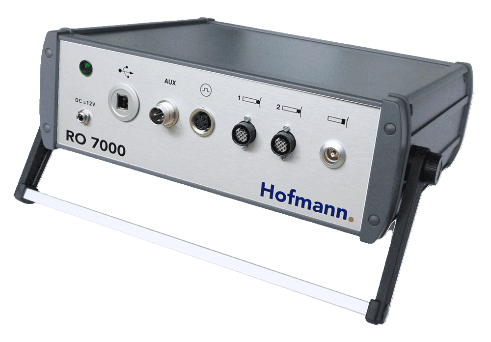
For flexible use on site, the portable runout test system offers RO 7000 fast and reliable measurement results. The mobile testing devices enable high measuring accuracy and therefore reduced production costs and help to optimize production processes in the long term.

Variants
Portable concentricity/runout test system
Horizontal concentricity/runout testing machine
Portable concentricity/runout test system
Type RO 7000
Concentricity and axial run-out are decisive parameters for the precision of rotating shafts and cylindrical components. Deviations from the ideal circular shape or plane are checked both during production and during repairs. With the RO 7000 portable concentricity and runout testing system, precise concentricity and axial runout measurements can be carried out on rotors, shafts and other cylindrical components in several planes. The rotor can be mounted in a lathe, on rollers or in prisms and can be driven manually or by motor. The system consists of high-quality measuring hardware for PC connection, a precise sensor set and the specialized concentricity measuring software "Orbistar".
Orbistar software - precise data acquisition and evaluation
The "Orbistar" concentricity measurement software supports the input of all measurement parameters, reliably records the measured values and creates complete protocols. At the same time, the software compensates for systematic influences caused by axial movements of the rotor. Special evaluation methods and the use of reference sensors ensure that the concentricity and axial run-out results are comparable and reproducible across different measuring systems.
Measurement of radial and axial run-out
The actual concentricity and axial run-out measurement is carried out using high-precision distance sensors, which are supplied with brackets for commercially available magnetic stands. The angular position of the rotor is recorded via an encoder, which is driven by the rotor itself via a friction wheel, or alternatively via a speed sensor.
Integrated runout measurement
A decisive advantage of the RO 7000 is the simultaneous measurement of the electrical runout together with the mechanical concentricity deviations. Tactile sensors are used for the mechanical runout and eddy current sensors for the total runout. The electrical runout, the difference between total and mechanical runout, indicates the systematic measurement error of an eddy current sensor. This measured value is particularly important for the inspection of measurement tracks used for shaft vibration analyses and rotor tests.
The RO 7000 concentricity and runout testing system is therefore an indispensable tool for precise rotor testing, axial runout measurements and quality assurance of rotating components in production, maintenance and repair.
Special features
- Measurement of concentricity and axial run-out
- Measurement of the mechanical and electrical runout
- Portable, universally applicable system
- Flexible and easy handling
- Compatibility with stationary Hofmann UHR rotary/run-out testing machines
- Orbistar measuring software
- Simple and intuitive Windows software
- Input of measurement settings, data analysis
and report generation directly at the measurement object
or offline - Simple data exchange between
various Orbistar users - csv file data export
- Compensation of the movement of the shaft axis for comparable measurement results
- Compensation of radial and axial rotor movements
- Display of the measured values as an x-y or polar diagram
or as a 3D diagram with several polar diagrams
in each case in relation to an axial rotor position - Measured value analysis such as order analysis, eccentricity etc.
- Editable report templates that can be adapted to customer specifications
Field of application
- Runout and axial runout measurements on rotors in
- Manufacturing
- Maintenance, repair and overhaul
- Precise angle measurement of the
- of the mechanical runout
- of the total runout
- electric runouts
- Checking the concentricity / runout of measuring tracks for shaft vibration monitoring in accordance with ISO 20816-1, API 610, API 612, API 617 or API 687
 Technical data sheets
 Videos
Runout RO 7000
Horizontal concentricity/runout testing machine
Type UHR
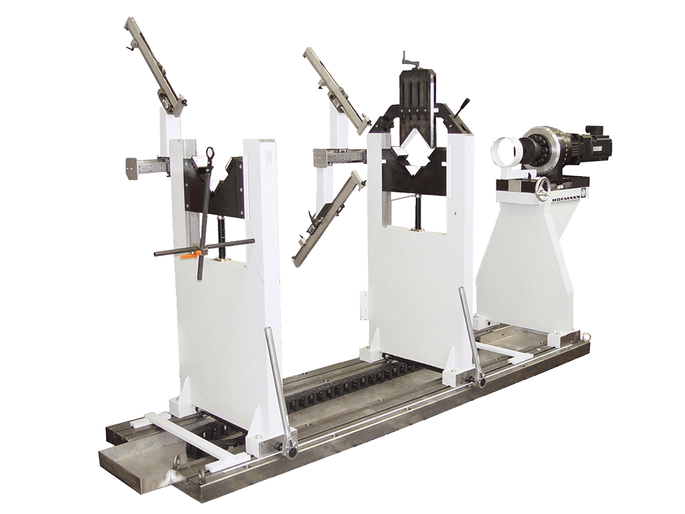
The Hofmann concentricity and runout testing machine type UHR enables precise measurements of concentricity and axial runout on rotors in several axial planes. For the measurement, the rotor is mounted in prisms and driven evenly and smoothly via a cardan shaft. The high-precision concentricity sensors are mounted on a movable measuring stand that is positioned along the rotor axis. The sensors can be adjusted radially to the respective rotor diameter and record the concentricity deviations at an optimum angle. The signals from the sensors and an encoder, which is connected to the drive, are recorded and processed by the powerful Orbistar concentricity measurement software.
Orbistar software - precise measurement data acquisition and evaluation
The Orbistar software supports the input of concentricity measurement tasks, records the data in real time, visualizes the results and creates detailed reports. Systematic measurement errors of prismatic bearings are automatically compensated. Reference sensors also ensure that axis movements of the shaft are correctly taken into account. The actual values obtained in this way can be reliably compared with the specifications so that any necessary corrections can be implemented precisely.
Runout measurement included
A special feature of Orbistar is the simultaneous measurement of the electrical runout. Mechanical runout (with tactile sensors) and total runout (with eddy current sensors) are measured simultaneously. The electrical runout is the difference between the total and mechanical runout and indicates the systematic measurement error of the eddy current transducer. This value is particularly relevant for checking measurement traces that are used for wave vibration measurements.
The horizontal concentricity and runout testing machine type UHR is therefore ideal for precise rotor testing, quality assurance and optimization of production processes as well as for use in maintenance and repair.
Special features
- High-precision, independent measuring device
- No blocking of machines for production due to concentricity/runout measurement
- Optimum access to the measuring tracks
- Measurement of concentricity and axial run-out
- Measurement of the mechanical and electrical runout
- Flexible and easy to use
- Orbistar measuring software
- Simple and intuitive Windows software
- Data analysis and report generation
- Compensation of systematic measurement errors
Typical rotor bearings - Display of measured values as x-y or polar diagram
or as a 3D diagram with several polar diagrams
in each case in relation to an axial rotor position - Measured value analysis such as order analysis, eccentricity etc.
- Editable report templates that can be adapted to customer specifications
Field of application
- High-resolution measurement of the shaft profile / concentricity / runout
- Precise angle measurement of the
- of the mechanical runout
- of the total runout
- of the electric runout
- Checking the concentricity / runout of measuring tracks for shaft vibration monitoring
according to ISO 20816-1, API 610, API 612, API 617 or API 687 - Testing of rotors in production
- Inspection of rotors before repair
Technical data sheets

Similar products
Horizontal, force-measuring balancing machine

Portable devices for measuring and balancing

Spin stand for electric anchor

Vibration monitoring and sensors
